
Overview
First, let’s talk about what was actually necessary for Planitia.
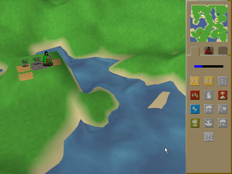
Planitia is a 3D real-time-strategy game, played from a 3/4 perspective. The terrain of the game world is a heightfield and a second heightfield is used to represent water. Units are presented as billboarded sprites (simply because I had no animated models I could use). Other game objects like the meteor are true meshes. So the Planitia engine needed to be able to render all of these at a minimum.
Planitia’s design presented some interesting challenges because the terrain of the entire map is deformable. The player (as a god) can raise and lower terrain to make it more suitable for villagers to live on. Earthquakes and volcanoes can also deform the terrain at just about any moment of play. Thus, it was necessary for the game to constantly check to see if the game world had significantly changed and regenerate the Direct3D data if it had.
Initializing Direct3D
Since this was my first Direct3D project, I deliberately limited the number of technologies that I was going to use. I decided that I would not use any vertex or pixel shaders since I didn’t want to start learning them until I felt I was familiar enough with fixed-function Direct3D. I also wanted to make the game friendly to older hardware and laptops.
To this end, I don’t do a lot of capability checks when I initialize Direct3D. But one check that I did find useful was the check for hardware vertex processing. If that capability check fails, it’s a pretty good indicator of older/laptop hardware and I actually make some changes about how the terrain is rendered based on it (that I will detail in a bit).
Vertex Structure and FVF
My vertex structure is as follows:
class Vertex
{
public:
	Vertex();
	Vertex(float x, float y, float z,
		DWORD color, float u, float v, float u2 = 0, float v2 = 0);

	float _x, _y, _z;
	DWORD _color;
	float _u, _v;
	float _u2, _v2;
};
And my FVF:
DWORD FVF = D3DFVF_XYZ | D3DFVF_DIFFUSE | D3DFVF_TEX2;
Notice that there are no normals. I’m using baked lightning for Planitia (as described in Frank Luna’s book – indeed, I used his code) and thus normals aren’t necessary. I am using two sets of UV coordinates because I “paint” various effects on top of the normal grass for the terrain (more on that in a minute).
Division of Labor – Creating the Index and Vertex Buffers
Okay, so what exactly is a Planitia map?
A Planitia map consists of a 64×64 grid of terrain cells. Thus, it must be drawn with 65×65 vertices. Each map has a heightfield of 65×65 values, as well as a 64×64 array of “terrain types”. Terrain types are identifiers I created that basically record what kind of terrain is in the cell. Values in the heightfield range from 0 to 8. If all four corners of a cell have a height of .2 or less, that cell is underwater has terrain type TT_WATER. If one corner of the cell is .2 but others are higher then the terrain type is TT_BEACH. Otherwise the terrain cell is TT_GRASS. Other terrain types like lava, flowers, ruined land and swamps are drawn over grass terrain and have their own terrain types.
And here’s my first fast/slow split. If I detect that hardware vertex processing is available, then each cell consists of five vertices – one each for the corners and one for the center. Drawing a terrain cell requires drawing four triangles.
If hardware vertex processing is not available, then I only use four vertices for each cell and only draw two triangles.
I set the UV coordinates across the entire terrain to the X/Y position of vertex in question. Thus the UV coordinates of vertex (0, 0) are (0, 0), the UV coordinates of (0, 1) are (0, 1), etc. This allows textures to tile properly while also giving me access to a few tricks (which I will get to in a minute). You’ll notice that this means that I’m not specifying what texture to draw with the UV coordinates – I do not have all my terrain textures on one big tile. That’s a good technique but I couldn’t use it for Planitia.
The diffuse color of each vertex actually stores two different sets of information. The RGB values are combined with the grass texture based on the lighting for that particular cell (again, using the pre-baked lighting code from Frank Luna’s book, page 224). The alpha value isn’t used for lighting. It’s actually used to create the beach effect, where sand blends evenly into grass. There’s more information on how this works in the Rendering section.
I actually create eight vertex buffers – one for each terrain type. Each vertex buffer contains data about the geometry of the terrain mesh and the shading of the terrain, but doesn’t contain any data about what texture to draw or how the vertices form into triangles.
Once the vertex buffers are done, I create index buffers to sort the vertices into triangles. Again, there’s an index buffer for every terrain type. And again, if hardware vertex processing is supported I create four triangles per quad; otherwise I only create two…but I use a technique called triangle flipping.
Triangle Flipping
Here’s how it works: for every cell in the terrain that you create, you test its upper-left corner against the upper-left corner of three other cells – the one diagonally up-left from the target cell, the one to the left of the target cell, and the one above the target cell.
If the difference between the target cell and the one to the upper-left is higher than the cell to the left and the one above, we flip the cell by specifying a different set of vertices to draw than the standard.
If you didn’t completely understand that, that’s okay. Here’s the code.
float diffA = abs(GetValue(x, y) - GetValue(x - 1, y - 1));
float diffB = abs(GetValue(x, y - 1) - GetValue(x - 1, y));
bool triFlip = diffA > diffB;
If triFlip is false, we create the triangles normally.

If the test is true, we create the triangles like this instead:

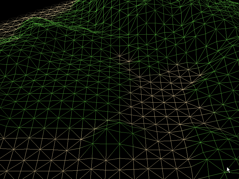
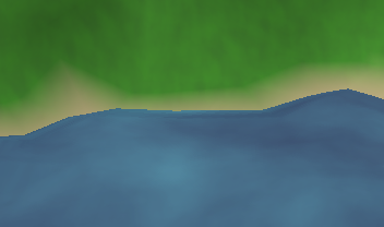
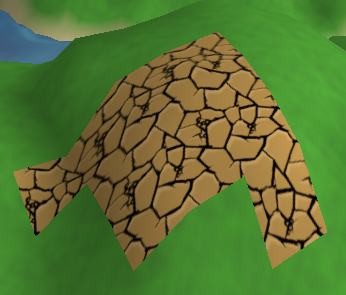
The results are pretty impressive. Here’s Planitia with two-quads-per-triangle without triangle flipping:
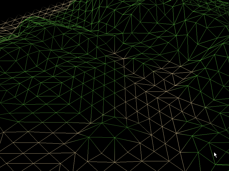
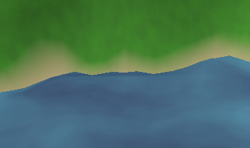
Notice all the jagged edges. When we use triangle flipping, they go away:
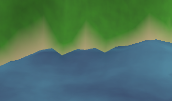
That’s much better – it gets rid of the spikes – but now we’ve got lots of straight lines and the coast looks a bit boring. Using a center point on our quads looks even better:
Now it looks smooth and interesting. Which is why I do that when the hardware supports it.
Drawing The Scene
All right, the vertex and index buffers are created and it’s time to actually draw the terrain. Here’s the procedure I use.
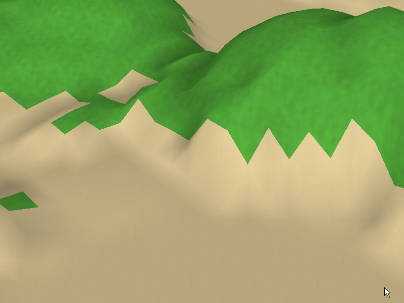
The first thing I do is to turn alpha blending off. Then I draw all eight of my vertex buffers. I set the texture to be drawn based on the terrain type I am drawing (this is why data about what texture to draw isn’t stored anywhere in the vertex or index buffers). If the terrain type is “water” or “beach”, I set the sand texture and draw it. If it’s anything else, I set the grass texture and draw it. The result:
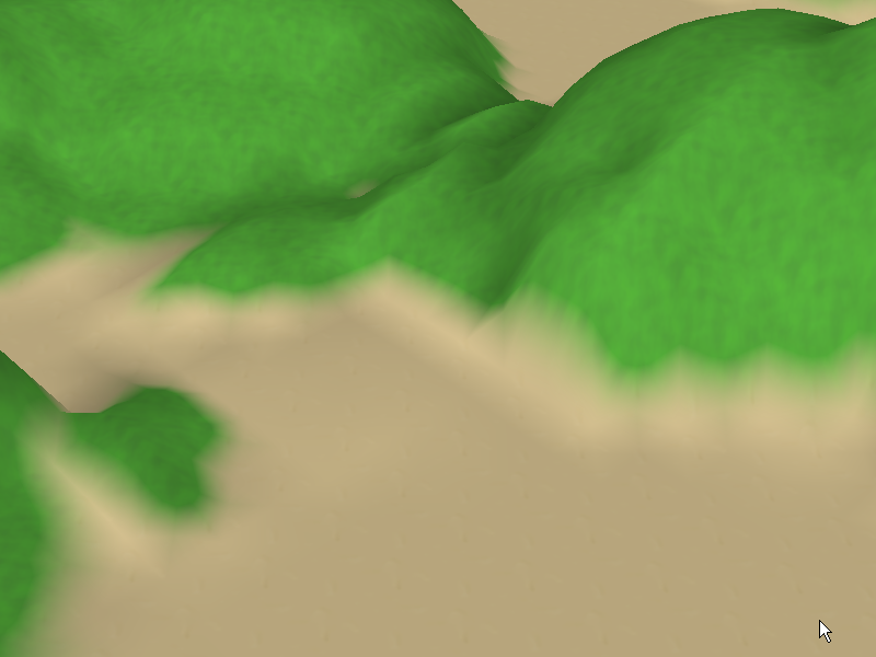
Time to do some blending. I turn alpha blending back on and set the grass texture as the active texture, and then I redraw the vertex buffer for the beach. Since blending is on, the grass is drawn fading out over the sand, resulting in a sand-to-grass effect. Now it looks like this:
This technique is called multipass multitexturing. Instead of…
Oh, good grief…
Must…resist…
Can’t…stop…
There. Got it out of my system.
Instead of using multiple sets of UV coordinates and setting multiple textures at once, you draw the same geometry twice with different textures. The upside of this is that it’s easy to do and very hardware-compatible. The downside is that you are drawing more polygons than you technically need to, but if you’ve got a good visibility test (which we’ll get to in a minute) it shouldn’t be a problem.
Alpha Masking
This is the one thing in Planitia that I’m proudest of (well, along with the water).
The other terrain types – lava, flowers, ruined land and swamp – are all drawn over grass and are masked so that the grass shows through. This is why I already drew these once with grass set as the active texture. But I’m using an additional trick here. These textures won’t get their alpha information from the vertices and they don’t have any alpha information of their own. They get their alpha information from another set of textures altogether.
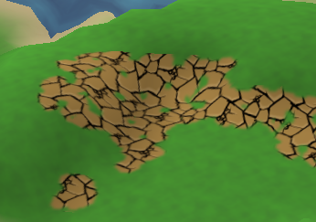
You see, practically any grass terrain cell can be turned into any of the other four types at practically any time during the game. If I simply draw the cell with the new texture, I get big chunks of new terrain on top of the grass:
I can alter the textures so that they fade out at the edges, but that still gets me soft tiles of terrain lined up in neat columns and rows.
What I really needed was for tiles that were next to each other to sort of glom together…and be able to do so no matter how they were configured.
Hmmm…
And then I remembered that I’d seen this problem already solved in Ultima VI! The slimes in that game would divide if you hurt them without killing them, but instead of making smaller slimes they’d make one big mass of connected slime. So I grabbed the Ultima VI tiles to take a look at how the Origin guys had done it.

Turns out that they had done it by disallowing diagonal connections, thus reducing the number of connection possibilities from 256 to 16, and then they had drawn custom tiles for each connection permutation. This would still look better than either of the previous two solutions.
So I fired up Photoshop and created an alpha mask texture based on the slime texture.

The thing was…I didn’t just want to burn this filter onto each of my terrain type textures. I had a couple reasons for this. First, it would make the terrain type textures very specialized. Second, I’d have to make them much bigger to handle the sixteen permutations. And third, it would mean I wouldn’t be able to make my lava move by altering its UV coordinates (more on that in a second).
So what I needed to do was to set two textures – the mask texture and whatever texture I was drawing with. I needed to tell Direct3D to take the alpha information from the mask texture and the color information from the other texture.
I’ve tried to keep this article code-light, but this was tricksy enough that I want to go ahead and post the complete code. So here it is!
First we set our lava texture to be texture 0 and our masking texture to be texture 1.
gp_Display->m_D3DDevice->SetTexture(0, m_LavaTexture->m_Bitmap);
gp_Display->m_D3DDevice->SetTexture(1, m_MaskTexture->m_Bitmap);
In the first texture stage state, we select both our alpha value and our color value to come from texture 0 (the lava texture). Note that I am modulating the color value with a texture factor – I’ll talk a bit more about that in a minute.
gp_Display->m_D3DDevice->SetTextureStageState(0, D3DTSS_ALPHAOP, D3DTOP_SELECTARG1);
gp_Display->m_D3DDevice->SetTextureStageState(0, D3DTSS_ALPHAARG1, D3DTA_TEXTURE);
gp_Display->m_D3DDevice->SetTextureStageState(0, D3DTSS_COLOROP, D3DTOP_MODULATE);
gp_Display->m_D3DDevice->SetTextureStageState(0, D3DTSS_COLORARG1, D3DTA_TEXTURE);
gp_Display->m_D3DDevice->SetTextureStageState(0, D3DTSS_COLORARG2, D3DTA_TFACTOR);
In the second stage we simply select the color value we already had (meaning the lava value) but we overwrite the previous alpha value with the alpha value from texture 1, which is the mask texture.
gp_Display->m_D3DDevice->SetTextureStageState(1, D3DTSS_COLOROP, D3DTOP_SELECTARG1);
gp_Display->m_D3DDevice->SetTextureStageState(1, D3DTSS_COLORARG1, D3DTA_CURRENT);
gp_Display->m_D3DDevice->SetTextureStageState(1, D3DTSS_ALPHAOP, D3DTOP_SELECTARG1);
gp_Display->m_D3DDevice->SetTextureStageState(1, D3DTSS_ALPHAARG1, D3DTA_TEXTURE);
The end result was that I could use one mask plus four terrain textures to get four terrain types that stuck together no matter how they were positioned.
UV Transformation
The ruin, flowers and slime terrain types are all drawn the same way in the manner I just described, but I did a little extra work on the lava to make it look better.
First, I turn off the diffuse color when I draw the lava using the following render states:
gp_Display->m_D3DDevice->SetTextureStageState(0, D3DTSS_COLORARG1, D3DTA_TEXTURE);
gp_Display->m_D3DDevice->SetTextureStageState(0, D3DTSS_COLOROP, D3DTOP_SELECTARG1);
This means that the lava is always drawn fullbright and isn’t affected by the baked-in lighting. This makes the lava seem to glow with its own light.
I enhanced this effect by using the texture factor. This is simply an arbitrary number that you can set and then multiply the texture color by. I alter it on a per-frame basis to make the lava brighten and darken, thus looking like it’s glowing. Again, this is simply a render state that you set.
gp_Display->m_D3DDevice->SetRenderState(D3DRS_TEXTUREFACTOR, D3DCOLOR_XRGB(redvalue, greenvalue, bluevalue));
And finally I use a UV transformation to offset the lava’s UV coordinates over time, causing the lava to look like it’s flowing. A UV transform is just what it sounds like – it’s a matrix that the UV coordinates are multiplied by before they are applied.
Now, warning warning danger Will Robinson. Whenever a Direct3D programmer starts using this feature for the first time they almost always get confused. They typically try (just like I did) to create a transformation matrix using D3DXMatrixTransformation() or D3DXMatrixTransformation2D() and they end up (just like I did) with a very strange problem – for some reason, scaling and rotation seem to work just fine but translation does not.
That’s because the UV transformation matrix is a two-dimensional transformation matrix and two-dimensional transformation matrices are 3×3 matrices, not 4×4. The scaling and rotation numbers are in the same place in both, but the translation information is on line 3 of the 3×3 instead of on line 4 like the 4×4. This is why scaling and rotation work but translation does not. Put your translation values into the _31 and _32 values in your D3DXMATRIX structure and it’ll work fine.
(Now you may be asking, “Why doesn’t D3DXMatrixTransformation2D() produce a 3×3 matrix?” Good question. I have no idea why, but it doesn’t.)
Here’s the result:
All of these little tricks were suggested to me by Ryan Clark. Except the alpha masking, which is the one thing I came up with on my own which is why I’m ridiculously proud of it.
A Good Raypicker Is A 3D Programmer’s Best Friend
You can’t really write a 3D game without a raypicker, and this is where I’m going to ding Frank Luna a few points. While he does present the concept behind raypicking and some of the math behind it, in the end he cops out and does a line/sphere test once the ray has been transformed into world space. This is accurate enough for picking objects in a 3D world, but it’s not accurate enough to pick polygons within an object, and that’s exactly what I needed. I needed to be able to tell exactly in what triangle (or at least what cell) on the terrain the user clicked.
I made some manual improvements to the raypicker but it never seemed great. So I used a little google-fu and came up with…well, it’s pretty much the perfect ray-triangle intersection test. C source is included, which I was able to drop into my code pretty much unaltered and I was amazed at how much better it worked without any discernable performance hit. Get it, use it, love it.
(Not) Seeing the Unseen
“But why?” you may ask. “Sure, raypicking involves some 3D math, but it doesn’t involve 3D rendering, now does it?”
Actually, it does, because you can use a raypicker to find out which parts of your world are visible and which aren’t, and only draw the visible parts.
Which means that when I talked about how I fill out the index buffers above, I left out a step. Sorry, but it’s a big step and deserves a section of its own.
I think the most important thing I learned on this project was just how slow drawing triangles is. It’s slow. It’s dog-slow. It’s slow as Christmas. Slow as molasses flowing uphill in January.
When I first started programming I thought that a Planitia map would be small enough that I wouldn’t have to do any visibility testing. But it turns out that you can test your entire game world for visibility and compile a list of the visible triangles in less time than it takes to just draw the whole world. Even if your world is just a little 64×64 heightfield and some billboarded sprites.
That’s how slow drawing triangles is.
In case I haven’t made my point, drawing triangles is damn slow and you should only do it as a last resort. It’s so bad that actually having to draw a triangle should almost be seen as a failure case. Your code should not be gleefully throwing triangles at the hardware willy-nilly. Indeed, it should do so grudgingly, after forms have been filled out in triplicate. And duly notarized.
“Enough!” I hear you cry. “We get it! Drawing triangles is slow! Now would you please tell us how you did your visibility testing?”
Oh, right, the visibility testing. Well, there are actually two techniques I use.
The first is a simple distance test from the center of each cell to the camera’s look-at point. If the distance is larger than 25 (an arbitrary number I arrived at through experimentation) the cell cannot possibly be visible. This very quickly excludes most of the terrain on the first pass. There are 4096 terrain cells in a Planitia map; this first pass will let no more than 1964 (25 * 25 * pi) of them through.
In this video I have drawn the camera back so that you can see the circle of passing cells that moves as the camera does.
Now, that’s good, but it’s not good enough. Typically fewer than five hundred cells are actually visible and the circle test still has us drawing almost four times as many. So all the cells that passed the first test now go to the second test, which involves the raypicking code. Actually, it involves the inverse of the raypicking code. Instead of projecting a ray from screen space into world space, we project a point from world space into screen space.
For each cell, I take its four corner points and then project each one from world space into view space and then into projection space. This “flattens” that point into a 2D point that represents the pixel that point would be drawn as on the screen.
If any of these four points are inside the screen coordinates (which for Planitia is 0, 0 to 800, 600) then at least part of the cell is visible and the cell should be drawn. If all four of the points are outside the screen coordinates then the cell is not visible and should not be drawn.
The function I use for this is D3DXVec3Project(); it makes this procedure very easy.
Again, I’ve drawn the camera back in this video so that you can see how the visible area moves with the camera.
Only cells that pass both tests have their indices added to the index buffer, and thus it is the index buffer that limits how many triangles are drawn. The final result? We only draw what can be seen – and the game runs a whole lot faster.
Old Man River
And now for the last bit – the water.
Planitia’s water is its own heightfield. It uses the same vertex structure and FVF as the terrain. It’s a four-vertex, two-triangle heightfield and I don’t use triangle flipping on it. It’s pretty darn simple.
On the other hand, I do use an index buffer for it so I can do the same visibility tricks I do for the rest of the terrain.
The heightfield is updated fifteen times a second. During this update new heights are calculated based on a formula that changes over time, thus the heightfield seems to undulate. Yes, I could have used a vertex shader, but please recall what I said at the beginning about limiting the technologies I’m using.
While an undulating heightfield is nice, if the texture doesn’t animate the water can look more like blue slime. Populous: The Beginning has this problem.
So the second trick is to get the water texture to animate, and that is all done with the UV coordinates. I am not using a UV transformation matrix like I did for the lava, because that transformation matrix is applied to every UV coordinate identically and I needed to be able to customize them. So the UV coordinates are all individually calculated. And then hand-dipped in Bolivia chocolate before being delivered in a collectible tin.

The first thing we do is to simply add the current game time in seconds to all the UV coordinates. That gets the water moving.
The second thing we do is to add a very little bit of the camera’s movement to the UV coordinates. This is subtle but works really well, especially if your water texture incorporates reflected sky. Basically it makes it look like the reflected sky is moving at a different rate than the water, which it would be in reality. In the following movie, look at the edges to see the effect most clearly.
Now for the really clever bit. I add the same offset that I’m using to make the water undulate to the UV coordinate for that vertex. That is, if my undulation function says that the vertex is .015 above the normal height, I add .015 to the UV coordinates of that vertex. This has the effect of making the texture seem to squash and stretch as it moves. I think this does more to actually sell the idea that the water is flowing than anything else.
Now for one more thing. I actually add the height of each vertex in the terrain heightfield to the UV coordinates in the water heightfield. This has the effect of making the water “bunch up” around the land.
I could probably improve the water if I added another heightfield on top of the existing one, moving faster and in a different direction. If I did that, I would probably move the camera movement to the top heightfield, since it represents reflection movement. I may do this at some point, but I think Planitia’s water looks good enough for now.
And I think that’s about it. Planitia will be released with full source code so there won’t be any mysteries about how I did anything. If you’ve read this and you’re trying to replicate something I’ve done and are having trouble, please feel free to contact me at anthony.salter@gmail.com. And good luck with your own 3D programming endeavors!
Couple things..
– You said you don’t want to use multitexturing, but you end up doing so with the alpha masks =)
Oh well, I doubt there’s any only-single-texture hardware out there anymore.
– I still think that the number of triangles rendered is ridiculously small with the current hardware, and it should be faster to just render the whole landscape than do visibility checks.. I think your bottleneck is the fact that you need to send the polygon data to the video card all the time – if it remained there (as ‘static’ data), things would be fast.
On the other hand that would mean that you’d need to figure out tricks to make the deformation animations and water, which in practice would probably mean vertex shaders.. =)
Now that I read my comment, it came out a bit too negative; congrats on getting things this far, and thanks for doing the writeup!
Wow, nice tutorial. Nice vids, nice work.
Well done, you’ve gotten very far in a short amount of time and you have a knack for explaining things. In a few years I wouldn’t be surprised if you started writing Game Developer Articles.
I have to second sol_hsa, though. If all of your texture and vertex data is living in VRAM, it should be far faster to draw your entire world than cull and send over the bus. unless you’re doing an insane amount of drawing.
I’m curious, do you have any metrics on how many polygons you’re drawing per frame?
In the end, if it’s fast enough for you then it’s fast enough. The optimization pit can destroy your schedule if you let it, stick with what you got if it works.
Wow, Ian…thanks for the kind words.
As for the frame rate…okay, okay. It’s entirely possible that I may have exaggerated how slow drawing triangles is just a little bit for humorous effect. After Sol helped me stop doing some incredibly stupid things my framerate became pretty much awesome and stayed there. Here’s a screenshot of NVPerfHud running on Planitia; according to it I’m drawing about 12000 tris a frame at 125 frames a second and my CPU, GPU and memory usage are all very low.
On the other hand, I do think that graphics programmers do need to be very selective in what they send to the card, since drawing triangles is comparatively slow.
Very nice tutorial and well written. I read it through and enjoyed every part!
Very insightful article, can’t really add to the discussion but in terms of performance, if it works for you, that is what is for the best 🙂
I’m nit-picking but I was a Direct3D driver programmer and a graphics programmer in a previous life. Those wounds are deep and the images still haunt me…
Drawing triangles, without complex vertex or pixel shaders, is cheap. Very cheap. A GeForce 4 has a theoretical maximum of over 30 million trangles/second. Your game is using 1.5 million triangles/second. What’s expensive in graphics programming is locking buffers (NEVER DO IT if you can avoid it) and state changes (texture and shader changes are the worst).
It’s actually cheaper to stitch polygons together with degenerate triangles and draw more per batch than it is to send multiple batches (up to a limit). Back in the software days, it was all about avoiding a rasterization. Now it’s all about avoiding render state changes and changing anything in VRAM from the CPU.
Again, you’ve already done the work to get excellent performance so there’s no reason to change anything now. I’m just being a jerk. :p
I think you guys are missing something: Viridian isn’t sending geometry to the card evrey frame. He’s only culling his index buffer. I’m pretty sure his verts are static.
And I wouldn’t expect culling to be a per-frame expense in a game like planitia anyway, because the camera isn’t usually moving. You don’t need to cull when your camera’s holding still 😉
Well, it WAS about avoiding buffer locks and state changes, now it’s about minimizing bus traffic and optimizing shaders.. =)
Yeah, but I don’t think we’re talking about a lot of bus traffic here…. those Indices are just two bytes each.
According to the post the world of Planitia is 64×64 tiles of four triangles each. That’s 16k triangles which is easily drawn without any form of culling. The problem is that the terrain needs to be drawn muliple times for each terrain type. Instead of culling tiles to the camera he could have gone the multitexture route.
My original point still stands, relative to changing buffers and some expensive renderstates, triangles are cheap. That’s all I’m trying to say.
To break out the broken record, it doesn’t really matter. He has the performance he wants.
One more sad reality must be faced in PC land: the most common 3D accelerators today are Intel’s integrated variety. They outsell both AMD and Nvidia!
Even though they support pixel shaders, these most-common GPUs don’t accelerate vertex operations at all. Every single vertex transformation is done on the CPU!
So if you’re optimizing for low-end PCs, limiting your vertex count remains the single most important thing to do.
If you’re aiming for dedicated gamers, then vertex count is less likely to be a bottleneck. But if you’re aiming for casual / low-end gamers, the situation is different.
I totally agree with your recommendation of multitexturing, BTW. It’s a definite win, especially for low-end harware where verts are expensive… but so is index culling 😉
Woohoo! Graphics programmer slapfight in my comments!
Viridian, maybe you answered this before but I was wondering if you were using SDL for anything in Planitia or just DirectX?
No, DirectX’s sprite library pretty much took the place of SDL. If I had used OpenGL I probably would have continued to use SDL as well, since they integrate, but I couldn’t do that with Direct3D. So SDL is out of my framework now.
i wanted to bring up a point i think might have been missed – his terrain ISN’T going to be static at all. doesn’t one of the requirements of building an index array or triangle buffer supposed to be that it doesn’t change? a major part of planitia (much like it was in populous) was the ability to shift the land up and down to shape it for your people. i think that means he needs to avoid as much vram buffering as he can. now i’m a newb and i’ve just learned how to use the vert buffs, so please correct me if i’m wrong on this.